Solutions
OEM Integration
Integrating a data-link module into your airframe and ground segment — electrical, mechanical, RF, and configuration work.
What this is
For an OEM or system integrator, a data link is not a product you buy — it is a subsystem you integrate. The questions that decide the project are mechanical (mass and volume budget), electrical (supply voltage, current, connectors), RF (antenna placement and cable losses), and software (configuration tooling and telemetry formats).
The catalog is structured for this: every published model lists supply voltage, power draw, mass, dimensions, interfaces, and the configuration tool it ships with. Micro and Standard series modules start at 34 g and 104 g respectively, and the J30 series exposes the fullest interface set (dual Ethernet, RS-232, TTL/UART, SBUS, RS-422) for platforms that need several subsystems on one link.
Selection factors
What to weigh before shortlisting a model.
Mass and envelope budget
Published modules run from 34 g (Micro series) to 435 g (long-range hopping units). Weigh the module plus its antenna, cabling, and mounting hardware — the radio is rarely the whole integration mass.
Electrical match
Supply voltages span 3.3 V-ish TTL domains up to 28 V aircraft buses depending on model, with maximum power from 3.6 W to 72 W. Check peak transmit current against your power system, not just average draw.
Interface plan
Map each onboard subsystem to a physical port: mission computer on Ethernet, flight controller telemetry on TTL/UART or RS-232, gimbal control on SBUS or serial. Models differ sharply here — the interface row of the comparison table is the decisive one.
Antenna placement
LOS reference range figures assume sensible antenna installation. Composite hatches, metal frames, and long coax runs all erode it. Plan antenna positions early; they are hard to fix late.
Configuration and pairing
Each series ships with its own configuration tool, and the ground-station units (VG02A, VG03A) pair with the airborne modules. Phase 1 data has incomplete ground-station parameters — flagged as such on the pages — so confirm details through the RFQ.
Honest guidance
- Interface names are not interface counts. 'Ethernet ×2' means two physical ports; verify the data sheet pinout for your board design before layout freeze.
- Some published ground-station units have incomplete specifications in the Phase 1 data (marked on their pages). Do not design around gaps — ask.
- Commercial fields (MOQ, lead time, sample policy) are not yet published. They are quoted per inquiry through the RFQ.
- Sample-first is the realistic path: integration risks (antenna, thermal, vibration) only show up on your platform, not in a datasheet.
Test footage
Recordings from the manufacturer's own test programme — bench, field, and flight tests, each shown with the conditions it was run under.
High & Low Temperature Test (VMF Series)
A VMF series unit cycled through the cold and hot ends of its storage and operating envelope in a climate chamber. The figures apply to this series, not to the catalog as a whole.
- Captured
- 2024-07-12
- Duration
- 1m38s
High & Low Temperature Test
A unit cycled through the cold and hot ends of its storage and operating envelope in a climate chamber.
- Captured
- 2024-04-19
- Duration
- 59s
Company Introduction
The supplier's corporate film, included for its production-line footage. Its narration claims in-house chip development and references military and police markets; this site makes neither claim.
- Captured
- 2024-07-12
- Duration
- 2m11s
Footage is published as recorded. Every distance figure that appears in a clip is the line-of-sight reference condition of that test, not a guarantee for your mission.
Matching models
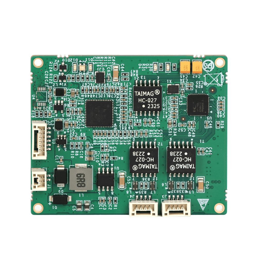
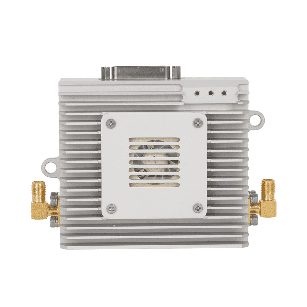
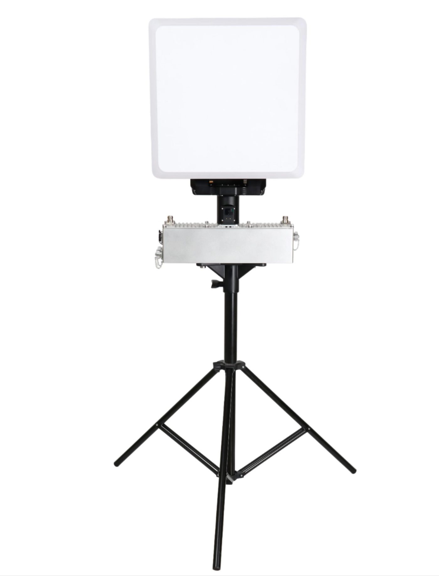
Published integration candidates: a micro module, a full-interface J30 module, and the VG03A portable ground station.
Related guides and solutions
Let's build your UAV data link solution
Send us your platform, required range, and payload — our technical team responds with a model recommendation or a quote.